
9 min read / Updated 2026-09-22
Prepared by the WireTorque catalog team
2006 GMC Envoy Wiring Diagram: Multiple Electrical Faults and Power-Loss Checks
A vehicle-specific diagnostic case file for a 2006 GMC Envoy with several electrical systems failing together, covering battery feeds, fuse-block inputs, ignition-switched power, ground distribution, data lines, and loaded voltage-drop testing.
Group the symptoms before opening the diagram
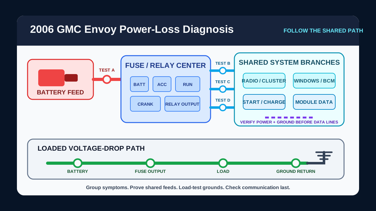
Write down every affected function and the conditions in which it fails: key off, accessory, run, crank, engine running, hot, cold, or after driving over a bump. A radio, instrument cluster, power windows, and warning lamps that fail together may share a feed, ground, ignition state, splice, connector, or module network even though they appear on different system pages.
Separate a complete power loss from an intermittent reset and from a no-communication complaint. Record whether the starter cranks normally and whether exterior lamps remain bright. Those observations help identify whether to begin at a high-current battery path, an ignition-switched branch, or a lower-current module circuit.
Confirm battery voltage and main connections under load
Begin with a properly charged battery and inspect both terminals, cable crimps, underhood power connections, and engine and body grounds. A connection can pass a small meter current yet fail when the starter, blower, heated glass, or several modules demand current.
Measure voltage drop while the affected circuit is operating. Test from battery positive to the supplied fuse-block input and from the relevant ground point back to battery negative. Use the exact diagram to divide a long circuit into sections instead of assuming that a visually clean connection is electrically sound.
Trace the shared fuse-block and ignition feeds
Use the 2006 Envoy power-distribution diagram to identify the source fuse, branch fuses, relay contacts, and ignition-switched outputs serving the failed systems. Test both sides of each relevant fuse with the circuit in the state where the fault occurs; looking through the plastic is not enough.
If several circuits lose power in one key position, compare constant battery feed with accessory, run, and crank feeds. Do not bridge unidentified relay terminals or install a larger fuse. Confirm terminal identity and current path from the diagram before bypassing any part for a controlled test.
Prove the ground path instead of relying on continuity
A shared ground with corrosion, a loose fastener, damaged splice, or strained terminal can make unrelated loads dim, reset, backfeed, or communicate intermittently. A continuity beep with the circuit off does not reproduce the current and vibration present during the failure.
Use the ground-distribution diagram to locate the common return path for the affected loads. Measure ground-side voltage drop while those loads operate, then inspect the connector, splice, fastener, and sheet-metal contact only after the measurement identifies the weak section.
Check module communication after power and grounds pass
If multiple warning messages or no-communication codes remain, verify power and ground at each affected module before testing the data lines. A module that is offline because it lost supply voltage can look like a network fault on a scan tool.
Use the computer-data-lines diagram to identify the correct communication pair, splice points, and participating modules. Keep the battery disconnected for resistance or continuity procedures when required by the service method, and do not probe supplemental-restraint connectors or force oversized probes into module terminals.
Use symptom changes to confirm the repaired section
After repairing a terminal, cable, splice, fuse-block connection, or ground, repeat the same load and key-state test that originally produced the fault. Confirm that voltage drop remains stable and that all related systems operate without resets or communication codes returning.
A repair is not proven by clearing codes alone. Recheck connector retention, harness routing, moisture protection, and charging voltage, then road-test only when the vehicle is safe and the original symptom can be reproduced without distracting the driver.
Questions buyers ask
Why would several electrical systems fail together on a 2006 GMC Envoy?
The systems may share a battery feed, fuse-block input, ignition-switched output, ground, splice, connector, or module communication path. Grouping the symptoms helps locate the shared part of the circuit.
Can a bad ground cause warning lights and module resets?
Yes. Excessive ground resistance can lower module supply voltage, create backfeeding, reset electronics, or interrupt communication. Test voltage drop with the affected circuits operating.
Should I replace the fuse block when several circuits lose power?
Not before testing. Verify battery inputs, ignition feeds, branch-fuse outputs, relay control, connector terminal tension, and loaded voltage drop to identify the failed section first.
Which diagrams help diagnose multiple 2006 GMC Envoy electrical faults?
Start with power distribution and ground distribution. Add starting and charging for battery or crank symptoms, and computer data lines when modules remain offline after their power and grounds are verified.