
6 min read / Updated 2026-08-29
Prepared by the WireTorque catalog team
OBD2 Port No Power: DLC Pin 16 Fuse, Ground, and CAN Wiring Checks
A short repair note for scan tool no-power and no-communication faults using OBD2 DLC pinout, fuse feed, chassis ground, signal ground, CAN, and exact vehicle wiring diagrams.
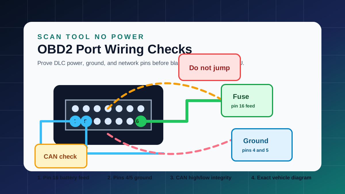
Start with the symptom at the scan tool
There are two common OBD2 complaints. In the first, the scan tool will not power up at all. In the second, the tool powers up but cannot communicate with one or more modules. Those complaints use different test paths.
For no power, begin at the DLC power and ground pins. For no communication, confirm the tool powers correctly, then use the wiring diagram to follow CAN high, CAN low, gateway power, module grounds, and network splice points.
Check pin 16 and the related fuse
OBD2 pin 16 is normally the battery power feed for the scan tool. If the scan tool is dead, check pin 16 with a meter, then identify the related fuse in the power distribution diagram.
Do not stop at visual fuse inspection. Test both sides of the fuse and confirm the terminal can carry power under load. A loose fuse terminal or corroded DLC wire can show voltage with no load and fail when the scan tool is connected.
Prove chassis ground and signal ground
Pins 4 and 5 are ground references on the DLC. A weak ground can create scan tool resets, unstable communication, or misleading voltage readings.
Use the ground distribution diagram to identify where the DLC ground path returns. If other dashboard, body, or network symptoms are present, a shared ground point may explain more than the scan tool complaint.
If power is good, move to CAN and gateway checks
A scan tool that powers up but cannot communicate may have a CAN bus fault, gateway module issue, missing module power, shorted data line, or a module pulling the network down.
The OBD2 connector shape is standardized, but the network layout is not the same on every vehicle. Use the exact year, make, model, and system diagram before disconnecting modules or testing network resistance.
Avoid risky shortcuts at the DLC
Do not jump random DLC terminals. Some pins may be manufacturer-specific, unused, or connected to sensitive module circuits. The connector view and wiring diagram should identify pin function before probing.
Use correct back-probing tools, avoid spreading terminals, and disconnect power only when the service procedure requires it. If airbags, hybrid systems, or high-voltage systems are involved, follow the applicable safety procedure first.
Questions buyers ask
Which OBD2 pin powers the scan tool?
Pin 16 is normally the battery power feed. If the scan tool is dead, check pin 16, the related fuse, and the DLC ground pins before blaming the scanner.
Which OBD2 pins are grounds?
Pins 4 and 5 are ground references. Pin 4 is commonly chassis ground and pin 5 is commonly signal ground, but the exact diagram should be checked for the vehicle.
Why does my scan tool power up but not communicate?
The fault may be in CAN wiring, gateway power, module grounds, a shorted network branch, or a module holding the bus down. Use computer data line diagrams to narrow the path.