
9 min read / Updated 2026-08-28
Prepared by the WireTorque catalog team
Fuel Pump Relay Wiring Diagram: Crank-No-Start Power, Command, and Ground Checks
A practical crank-no-start diagnostic guide for fuel pump relay circuits, fuse feeds, PCM command, inertia switch paths, pump voltage, connector checks, and ground testing.
Confirm the complaint before testing the fuel pump
A crank-no-start condition means the starter rotates the engine but the engine does not run. Before opening the fuel pump relay circuit, confirm whether the engine has no fuel pressure, no injector pulse, no spark, no RPM signal, or a security-related enable problem.
The fuel pump circuit is only one part of engine-start logic. Many vehicles use PCM command, anti-theft authorization, crash or inertia switch logic, relay control, fuse protection, and shared grounds. The exact wiring diagram keeps the test path focused on the real control design.
Split the relay into control side and load side
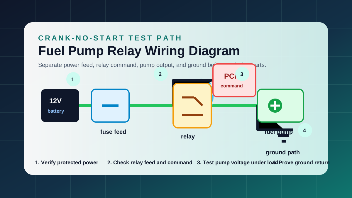
A fuel pump relay has a control side and a load side. The control side is usually commanded by the PCM or another module. The load side carries power from the protected feed through the relay contacts toward the pump.
A relay click does not prove the pump is receiving current. No click does not prove the relay is defective. Use the diagram to identify the feed terminal, command terminal, switched output, and ground or control return before jumping any terminal.
Check fuse feed and relay output under load
Start by checking the protected power feed at the fuse and relay. Test both sides of the fuse under the same condition, then check whether relay output appears during key-on prime or engine cranking.
Open-circuit voltage can mislead the diagnosis. A corroded terminal or weak relay contact may show voltage with the pump disconnected but fail when current flows. When possible, test the circuit while the pump is connected or with a safe load method approved for the vehicle.
Verify PCM command before blaming the relay
Many vehicles run the fuel pump for a short prime after key-on, then continue running it only when the PCM sees engine rotation. If the crankshaft sensor signal is missing, the PCM may stop commanding the pump even though the relay and pump are good.
Use engine performance and ECU pinout information together. If relay feed is present but command is missing during cranking, check crank signal, PCM power feeds, grounds, anti-theft status, and related enable inputs before replacing the relay.
Do not ignore inertia switches, crash logic, and connectors
Some vehicles include an inertia switch, fuel shutoff circuit, fuel pump driver module, rear body connector, or crash-event logic in the pump feed path. The wiring diagram shows whether the pump receives direct relay output or passes through another device first.
Rear harness connectors and pump-module terminals can suffer from moisture, heat, loose pins, or previous repair damage. If relay output exists but pump voltage is missing, follow the connector path step by step instead of replacing the tank unit immediately.
Test the fuel pump ground as a loaded circuit
A pump needs both power and a low-resistance ground. A weak ground can cause low pressure, intermittent starting, slow pump speed, or repeated pump replacement. Voltage-drop testing on the ground side during pump operation is more useful than a simple continuity check.
Use the ground distribution diagram when the pump shares a ground point with rear lamps, body modules, or other loads. Multiple strange rear-body symptoms can point to one shared ground instead of several failed components.
Use results to choose the next diagram
If feed, relay command, relay output, pump voltage, and ground are correct but fuel pressure is still absent, the pump assembly or in-tank connection becomes more likely. If command is missing, move to crank sensor, PCM power, anti-theft, or engine performance diagrams.
If the fuse opens repeatedly, stop replacing the fuse and move to short-circuit isolation. A shorted pump, rubbed harness, damaged connector, or pinched rear body wire can all overload the protected branch.
Safety notes for fuel pump electrical testing
Fuel systems involve fire risk. Work in a ventilated area, keep sparks and open flame away, use properly rated test equipment, and follow vehicle-specific pressure relief and service procedures. Do not bypass a relay or protection device unless the service procedure allows it.
This guide explains how to think through the circuit. It does not replace vehicle-specific service information, safety procedures, or professional judgment when fuel, high current, airbags, or crash-related circuits are involved.
Questions buyers ask
Can a fuel pump relay click and still be bad?
Yes. The relay coil can click while the load contacts are burned, high resistance, or missing feed power. Test relay output under load before deciding.
Why does the fuel pump run for only two seconds?
Many vehicles prime the pump briefly at key-on, then continue only when the PCM sees engine rotation and valid enable conditions. That behavior can be normal.
Can a bad crankshaft sensor stop fuel pump command?
Yes. If the PCM does not see engine RPM during cranking, it may stop fuel pump command and injector control. Check engine performance diagrams and scan data.
Should I replace the fuel pump before checking wiring?
No. Confirm fuse feed, relay command, relay output, pump connector voltage, and ground voltage drop first. Those checks prevent unnecessary pump replacement.