
9 min read / Updated 2026-09-18
Prepared by the WireTorque catalog team
2010 Dodge Charger Fuse Box Diagram: Starter Fuse and No-Crank Checks
A vehicle-specific diagnostic case file for a 2010 Dodge Charger that will not crank, covering the engine-compartment Integrated Power Module, 30A starter fuse, start request, relay control, starter solenoid feed, battery cables, and grounds.
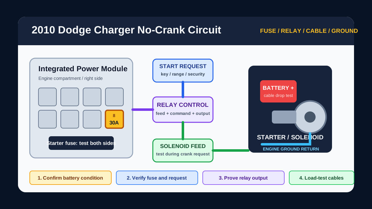
Identify the exact starting symptom first
A silent no-crank, one solid click, repeated rapid clicking, and slow cranking do not point to the same part of the circuit. A silent no-crank keeps the start-request and relay-control path high on the list. A solid click moves attention toward the solenoid, starter motor, battery cables, engine ground, or mechanical load.
Confirm battery state before opening the fuse box. Low system voltage can create relay chatter, warning lamps, and module behavior that looks like a control-circuit fault.
Start at the engine-compartment Integrated Power Module
The official 2010 Dodge Charger user guide places the Integrated Power Module in the engine compartment on the right side near the washer-fluid reservoir. It contains fuses and relays, including a 30A starter fuse listed at cavity 8 for the standard 2010 Charger guide.
Confirm the vehicle and fuse-box cover match before relying on a cavity number. Equipment and market variations can change assignments, so compare the cover legend and exact power-distribution diagram for the car being tested.
Test the starter fuse on both sides
Do not judge a fuse only by looking through the plastic. With the circuit in the correct test state, verify power at both fuse test points and check for voltage drop across the fuse or its terminals.
If the starter fuse is open, replace it only with the specified rating. If it opens again, stop and trace the protected branch for a shorted solenoid feed, damaged harness, water intrusion, or internal load fault. Never substitute a larger fuse or bridge the cavity.
Follow the start request before jumping the relay
The starter path can depend on ignition-switch request, park or neutral recognition, security authorization, module logic, relay control, and the high-current output to the starter solenoid. The exact wiring diagram shows which side of the relay is feed and which side is controlled.
Use a scan tool when available to check start request, transmission range, and security status. Do not bypass relay terminals at random: an incorrect jumper can damage the power module, wiring, or control electronics and can make the vehicle move unexpectedly.
Prove relay output and solenoid feed under load
If the relay command is present, test whether voltage leaves the relay path and reaches the starter-solenoid terminal during a crank request. A meter can show battery voltage on an unloaded wire that collapses when current is demanded.
Back-probe only identified terminals and keep clear of moving components. If the control side works but the output is missing, inspect the relay or integrated power path. If output reaches the starter, continue with cable, solenoid, starter, and ground testing.
Measure the battery cables and grounds during cranking
Measure voltage drop from battery positive to the starter feed and from the starter housing or engine block back to battery negative while the crank request is active. Excessive drop reveals resistance that a simple continuity test can miss.
Inspect battery terminals, engine-to-body grounds, starter fasteners, cable crimps, and heat-damaged sections near the exhaust. A clean-looking cable can still be corroded inside the insulation or crimp.
Use the diagram set that matches the failed stage
Use the 2010 Charger power-distribution diagram for fuse and relay feeds, the ground-distribution diagram for return paths, and the anti-theft or engine-performance diagrams when start permission or module communication is missing.
If the engine cranks normally but will not run, move away from starter-fuse diagnosis. That is a crank-no-start problem and requires fuel, ignition, crank-signal, engine-control, and power-distribution checks.
Questions buyers ask
Where is the 2010 Dodge Charger fuse box for the starter circuit?
The official user guide identifies the engine-compartment Integrated Power Module on the right side near the washer-fluid reservoir. Confirm the cover legend and exact vehicle diagram before testing.
Which fuse protects the 2010 Dodge Charger starter circuit?
The standard 2010 Charger user guide lists a 30A starter fuse at cavity 8. Verify the vehicle configuration and fuse-box legend because equipment or market variations can differ.
Can a good-looking starter fuse still be faulty?
Yes. A fuse or its terminals can have a crack, heat damage, or poor contact that is not obvious visually. Test both sides and verify the circuit under load.
What if the starter clicks but the engine does not turn?
A click suggests the command may be reaching the solenoid. Test battery condition, positive-cable voltage drop, engine ground drop, solenoid feed, starter motor, and mechanical load before replacing control modules.